A relay is a component that uses a electromagnetic switch to create contact between wires. There are 2 relays we used. A two switching circuit and a one switching circuit.
These are the terminals and what they do.
86 - positive side of control circuit
85 - negative side of control circuit
30 - battery supply for switched circuit
87 - open circuit when relay is off
87a - Closed when circuit is off
A low amp current goes through 86, through windings around an iron core creating an electro magnet and out terminal 85 to ground.
This electro magnet pulls a pin/switch down onto the contacts 30 and 87 completing the circuit and turning on any components wired to the 87 side side of the relay.
In the off position the relay recieves voltage but doesnt consume any between 86-85 there is no resistance because the relay is not on. there is no voltage in terminal 87 because the contacts are open and cannot recieve any voltage.
When the switch is on the relay is consuming voltage and none is left when it gets to terminal 85. There is now full available voltage at 87 because the switch is closed.
Tuesday, 19 April 2011
Logic probe/diodes
We made a logic probe which uses Light emiting diodes to indicate whether it is the positive side or negative side.
Diodes work only by letting electricity flow one way through the circuit. This is what makes the logic probe work.
When the positive and negative leads are hooked up to the power supply, I touched the probe to the positive side and the green LED went out. This indicates to me that this is the positive side. The opposite happened when I touched it to the negative side, the red LED went out, indcating to me this is the negative side.
The reason Why this happens is because electricity can only flow one way through a diode. When the positive terminal is touched this creates a short circuit and only allows the current to flow through the red LED and not the green one. When the negative side is touched there is another short circuit and this time it goes straight to ground before it can go through the red LED.
Also when each LED goes out the other one gets brighter. This is because they are wired in series and are sharing the voltage. When one isn't being supplied voltage the total available voltage is supplied to the one that is lit and it glows brighter.
Starter motor
The first test we carried out on the starter motor was a visual test to check for any burning, overheating, poling and physical damage. There was none of this except for very minor scratching.
Testing if there is a short circuit between the commutator segments and the armature core. I placed the multimeter set to Ohms on the two. The reading was infinite telling me there is no short circuit and that is what it was supposed to be.
Checking continuity between the comutator segments. Place one probe one of the segments and with the other move it around the others checking if there is a break on any of them. There was continuity in all of the segments.
Measuring the commutator I should have gotten in the range of 26.8 and 31mm. I got 31mm. The mica undercut should have been between 0.7 and 1mm. I got a measurement of 1mm.
Testing for runout on the armature shaft I placed the armature between two 'V' blocks. I rotated the armature 360 degrees while reading the dial test indicator (it is set up on the armature core). The runout should be no more than 0.2mm. I got a maximum reading of 0.1mm.
We also tested continuity and grounding in the field coils.
The brushes should be no less than 5mm. All of the brushes were greater than the specified length.
Alternators
Alternators are what powers the cars eletronics and charges the battery when the car is running. It is run straight from the crankshaft by a belt.
The first test we did was a visual check for any damage on the outer case. Then we removed the rear cover to expose the components. we then removed the brushes, the regulator and the rectifier.
I carried out a test to make sure the rotor shaft and the slip rings have no circuit between them. I placed the multimeter set to Ohms, one lead on the rotor shaft and one lead on the slip rings. The meter should read infinity meaning that there is no circuit between the two. There was no circuit.
Testing the rotor winding internal resistance I touched one lead to one slip ring and the other lead to the other slip ring. The reading should be within 2 and 6 Ohms. I got a reading of 2.8. This was a suitable reading which means it has passed.
Testing the stator winding resistance I connected the black lead to the common point and then touched each of the other terminals one after the other. the readings should be within 0.0 and 0.2 ohms. I got a reading of 0.0 Ohms. Then to test the stator winding to ground I attached the red lead to the common terminal and the black to the body of the altinator. There should be no connection so the reading should be infinite. This is what I got so there is no connection between the stator windings and the altinator body (ground).
Testing the rectifier diodes. Setting the multimeter on diode test mode I placed the common lead on the B terminal and touched the positive lead to each of the P terminals (where the diodes conect to the stator windings). I recorded my readings. The readings were all within the specs of 0.5-0.7 except one. The one that failed I got a reading of infinity, this was because it was the common point and has no connection to the B terminal.
If I put the cables on the opposite terminals I got an infinite reading for all of the diodes. This is beacause diodes only let electricity flow one way in a circuit.
Testing the Negative diodes is almost the same only touching the negative lead to the E terminal (body of the rectifier) and the postive to each of the P terminals. I should have got an infinite reading for each of the diodes which I did. Testing with the leads swapped over, I got readings which were in the specs of 0.5-0.6.
Measuring the brushes they should all be above the minimum length of 4.0mm. My brushes were both at 6.0mm.
Batteries
When we first got the batteries there were 2 terminals (one positive and one negative) and several screw caps. These screw caps let you get to the electrolite inside.
The first test we did was a visual inspection of the battery for corrosion and deformation/warping of the battery. We also should make sure there is no leakage of electrolite and the battery clamp bolts are tight. If there was some corrosion on the terminals we would need to clean it with some water and baking soda.
Another visual check was of the electolite levels. If they were just covering the plates inside then they were at a satisfactory level.
Checking the OCV (open circuiut voltage) we put the voltmeter accross the terminals on the battery.
Anything under 12.4V you would have to charge the battery before continuing with testing. My battery was 12.8V so I could continue with testing.
Next test is the specific gravity test. This is the difference between the highest hydrometer reading and the lowest. My specific gravity variatin was 0.1 which is in the good range (0-0.5)
Next was the high rate discharge test. The CCA (Cold Cranking Amps) of my battery was 410A. This means I have to apply a load of 205A (half the CCA). The voltage of the battery must hold above 9.5V while the load is applied for 15 sec.
The voltage held while the load was applied was 10V which is a pass.
The parasitic draw test is when you attach a multimeter set to amps in series with the battery circuit. The ammount allowed is 0.3mA. My result was 0.25mA which is ok.
Sadly we did not get to do any work with a digital battery tester.
Compound circuits
I didnt quite understand the workings of the compound circuit but here is what I found out.
There is two bulbs wired up in parallel and 1 in series.

When I wired it up at first the bulbs in the parallel circuit were hardly lit and the series bulb glowed bright.
I think this was because the series bulb was wired after the parallel circuit and because the resistance of the parallel was less than that of the series it used all of the voltage to power it leaving very little for the parallel bulbs resulting in them not lighting up.
Parallel circuits
Parallel circuits consist of more than one bulb. They have there own positive supply of electricity and there own earth.
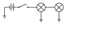
With each bulb having their own positive supply they recieve the full available voltage from the power supply. This means that they will glow at their full brightness.
When measuring the available voltage at each bulb, they both did recieve the full power supply voltage.
The amperage flowing through bulb 1 and 2 was 0.73 A. The total amperage flowing in the circuit was 1.46.
This means that amperage is shared in the circuit, but it is higher due to both of the bulbs amerage's being added together (and the amperage at each one being what is sufficiant to light the bulb) to get the total circuit amperage.
Calculating total resistance in a parallel circuit, you put 1 over each of the values. Eg 1/16.42
These are added together. Eg 1/16.42 + 1/16.41
Then you put 1 over the answer. Eg 1/0.122
You will then get your answer. = 8.20
Adding a third light bulb in parallel increases the total amperage in the circuit but all bulbs still recieve the total available voltage from the power supply. So for every consumer added in parallel the total amperage will increase.
Series Circuits
A series circuit is a circuit with more than one component in it that are wired up one after the other.


When I measured the Voltage drop after light bulb 1 it had dropped by 6.05 V. After light bulb 2 I measured it and it was 5.86 V. This shows that when you have 2 consumers wired up in series they share the voltage between them.
The amperage in the series circuit is lower than that of the individual. This is because with 2 bulbs there is a higher resistance resulting in the amperage being lowered.
Three light bulbs in the circuit resulted in the voltage at each bulb dropped even more. This is because there are now 3 bulbs sharing the same voltage.
Again the amperage is even lower because there are more consumers in the circuit creating a higher resistance.
Each time I added a bulb to the circuit the brightness of each one got dimmer. This is because the voltage is being shared and each one is not recieving the maximum to sufficiently light it.
Individual Circuits
Individual circuits contain 1 consumer and a power supply to supply voltage for the consumer to use.
 The individual circuit we built had a 12V power supply, a fuse, a switch and a single bulb.
 We hooked up the power supply to the fuse first to prevent voltage spikes from blowing out the bulb. Then the fuse was wired to a switch so I could turn the circuit on and off without removing wires. The switch was wired off to a bulb which went back to ground. (back to the power supply)
We used a voltmeter to measure the available voltage at different points in the circuit.
(available voltage means how much voltage is being supplied when measured after different components)
Positive terminal on the 12v supply = 12v
Terminal before switch = 11.97v
Terminal after switch = 11.97v
Terminal before light bulb = 11.96v
Terminal after light bulb = 0v
Negative terminal on the 12v supply = 0v
The cause in voltage drop between the positive terminal and the terminal before the light bulb could be caused by corosion/bad conection at the postive terminal, fuse and/or switch. (creates a resistance that the electicity has to pass through using some voltage).
The voltage drops completely after the lightbulb because it is the main consumer in the circuit and uses up all of the available voltage.
We measured the amps by putting the multimeter on the amps scale and wiring it up in series.
Total Ohms (resistance) in a component was calculated by using Ohms law. Volts divided by Amps. In the light bulb the total resistance was 35.29 Ohms.
The Wattage used by the light bulb was calculated by using the Power law. Volts times Amps. The Watts used at the light bulb were 4.08 W.
We placed a larger bulb in place of the smaller one. It used the exact same amount of voltage as the smaller bulb (consumers use all the available voltage). There were more amps running through the circuit (0.72 A) because the bulb has less resistance (16.66 Ohms). So this means the Wattage (8.64 W) will be larger because the amperage is greater.
Subscribe to:
Comments (Atom)